Map Sensor Wiring Diagram – A fully functioning MAP sensor is necessary to maintain the right combination of acceleration, fuel economy, emissions and engine smoothness. When the throttle is wide open and air is rushing into . A five-wire oxygen sensor is considered a wideband sensor. Traditional oxygen sensors have only one or three wires. The five-wire system allows the sensor to process more information, in turn creating .
Map Sensor Wiring Diagram

Source : www.youtube.com
MAP Sensor Wiring | Team Integra Forums
Source : www.team-integra.net
MAP Sensor wiring colors | GMC Acadia Forum

Source : www.acadiaforum.net
Toyota map sensor pinout

Source : in.pinterest.com
Alky kit with Dpe map sensor? CorvetteForum Chevrolet Corvette
Source : www.corvetteforum.com
MAP Sensor Wiring Diagram: Learn How to Connect Your Car Sensor

Source : www.tiktok.com
GM 3 bar map sensor calibration G4+ Forums | Link Engine

Source : forums.linkecu.com
MicroSquirt® Introduction
Source : www.useasydocs.com
Clemson Vehicular Electronics Laboratory: AuE 835 Student Project
Source : cecas.clemson.edu
MAP Sensor & Wiring Diagram YouTube

Source : www.youtube.com
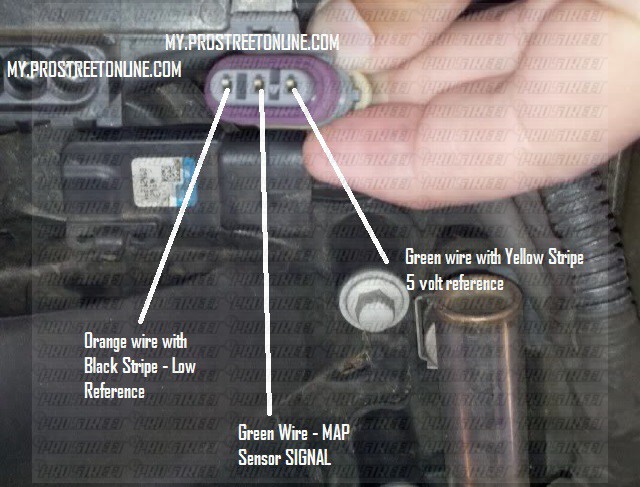
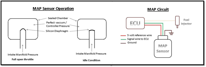
Map Sensor Wiring Diagram MAP Sensor & Wiring Diagram YouTube: A manifold absolute pressure sensor (MAP) is one of the sensors used in an internal combustion engine’s electronic control system. Engines that use a MAP sensor are typically fuel injected. The . You can use the outcome of your affinity diagram (your highly organized set of data) to: Inform the creation of empathy maps. Build personas that represent your target audience in the best possible .